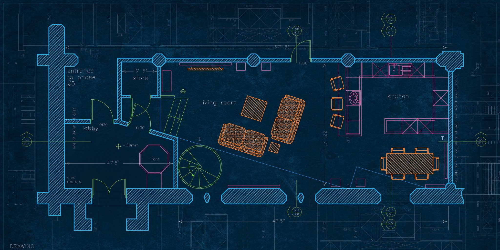
Autodesk A Design In The Middle Of The Build Plate
Balance unequal stresses PSI at joints by using the stress. To align to reorient and align planer faces.

3d Portal Frame Building Tutorial In Autodesk Robot Structural Analysis Youtube
The Benefit of Parametric Modeling.

Autodesk a design in the middle of the build plate. Should you decide at a later time that the hole shouldnt be centered on. No time needed to tram in anything. If the size of the face is changed the hole stays centered retaining the original design intent.
You can apply the other rotational DOFs and all the translational DOFs as needed. You can model it in Advance but you are the one driving it it goes where you steer it. Click the Save button on the top panel bar and.
If I gave you a model of a 50mm by 50mm by 6mm steel plate with an M10 clearance hole through the middle of the face and asked you to change the width of that plate what should happen to the hole. Using feature-based modelling we can decide how our model will change this is known as Design Intent. The cutting punch punching the.
The result - teams stay on schedule and on. One of our Autodesk construction ecosystem partners HoloBuilder provides a virtual tool that allows you to easily capture view and control project progress with 360 degree photos from anywhere. What is a Plate Element Plate elements are three- or four-node elements formulated in three-dimensional space.
Under the Modify menu select Align. Given its firmware is Marlin. This is awesome for building models.
Choose the top face of the plate and then the supplied Autodesk logo as an input for the command. You may have to click the word Modify on the ribbon to reveal this command if. Ill attach a couple of screenshots of how my control looks like when I insert the gcode.
Autodesk Inventor allows us to build parametric models. Pick a planer face on the body or component. The next action to take is to set up the slicer in such a way it matches the origin of the printers firmware.
A world-leading design engineering and project-management consultancy. Our lived environment is facing rapid change. Thus keeping the nozzle in a different position.
Or building families of components that are very similar copy and paste adjust a parameter job done. These elements are used to model and analyze objects such as pressure vessels or structures such as automobile body parts. Its just like floating in mid-air.
Placing a hole centered on a face couldnt be any easier. Select the Decal command from the Insert dropdown menu 15. Because of my control I cant really see if it is in the build limits or what exactly is happening.
If the slicer isnt configured properly a different point of origin will be assumed. The gray zone represents the build plate of the machine. With this tool it is possible to be made of a circular plate slice a cap with a hole in the middle.
Isnt there any other ways in Fusion making the gcode so the model is in the middle or so. Step 4 Connect plates together again. Use the diagram below as a reference for the detailed descriptions that follow.
To face these challenges we are radically transforming the way infrastructure is designed delivered and operated. If the aligned component is part of an assembly it may be necessary to use a Rigid Group to move them all at the same time. Im not sure which update corrected this behavior but in a previous release when you changed the size of the face the hole location didnt update to maintain the design intent.
In the case of Delta and Cartesian printers it is the center. When using macros if you create a joint and think you may use it again somewhere store it in the table with a suitable. Blue zones represent the XY area that each gantry can access.
The line defines the end of the flat top so if you want the overall width to be 20mm with an internal bend radius of 2mm and a plate thickness of 5mm you would need the line 13mm from the YZ plane. You will need to make a sketch on the surface of the plate and draw a line at the point where you want the bend to start. Learn how to apply and communicate Design Intent in this post on the official Inventor Blog by Paul Munford.
For this purpose the sheet is inserted and deep-drawn through the drawing die. Place and scale the logo symmetrically using the triad indicator as shown. These areas are shown shrunk and offset in the Y-direction for clarity.
The Problem with Parametric Modeling. Autodesk Inventor allows us to build parametric models. They explain how Forge integrates job site data with design models allowing teams from anywhere to compare real-world conditions with BIM.
Expand the Metal group and drag the Gold material you like to the plate in the graphics area to assign it. Usually it would be found on the left front corner of the build plate. Gantry Settings The settings are accessed using the Gantry Settings button for the Generic Multi-Gantry FFF workspace.
I think the origins line up in the x and y directions but it might just look like that. Try to use Macros where possible for Joints. Models that can easily change by adjusting the value of a parameter.
Assess your project before you start look at how you are going to build the structure how it is going to be delivered where are you starting from cranage etc. Determine plate loads in the plane of the plates in pounds per linear foot as resulting from slab loads. A fixture plate design that the 5 axis vise is fixed to the plate self centers on the Haas TR210 B axis table and is keyed as well.
Ready for machinist to simply load add 3 bolts and it is set and ready to run the CNC program. This is awesome for building models that need to be adjusted in a predictable fashion configurable designs. The chicken coop design project encourages students to use their imagination to design a useful attractive structure that improves the way chickens live and the way they are integrated into the environment.
The problem with. Models that can easily change by adjusting the value of a parameter. The out-of-plane rotational DOF is not considered for plate elements.
Our aim is to help create a world that is diverse sustainable full of thriving communities and working better for. Step 3 Figure 41c Consider plates disconnected at ridges and valleys find extreme fiber stresses in pounds per square inch at the center line of plate span. Students are challenged to solve such design problems.
Imagine a space-age solar-powered chicken coop resting on the roof of a twenty-five story building in the middle of a booming metropolis.

Maya Structures Procedural Building Generator Tool For Autodesk Maya Building Autodesk Structures

How I Would Sketch 80 20 Rails Fusion 360 Tutorial Larslive 152 Solidworks Tutorial Fusion Autocad Isometric Drawing

Dessin D Architecture Logiciel De Conception Architecturale Autodesk

Autodesk Empowers Innovators Everywhere To Make The New Possible Design Suites Autocad Training Autocad

Fusion 360 How To Cut One Body From Another Youtube

Autodesk Inventor 2013 Drawing Projected Section View Tip Design Motion Autodesk Inventor Inventor Autodesk

Learn To Create Common Woodworking Joint In Autodesk Fusion 360 In This Step By Step Easy To Follow Fusion360 Tutorial We L Woodworking Joints Joint Fusion

How To Design 3d Population Maps Using Tinkercad Scale Drawing Map Design

Autodesk Inventor Tutorial Ball Bearing Youtube Autodesk Inventor Inventor Tutorial

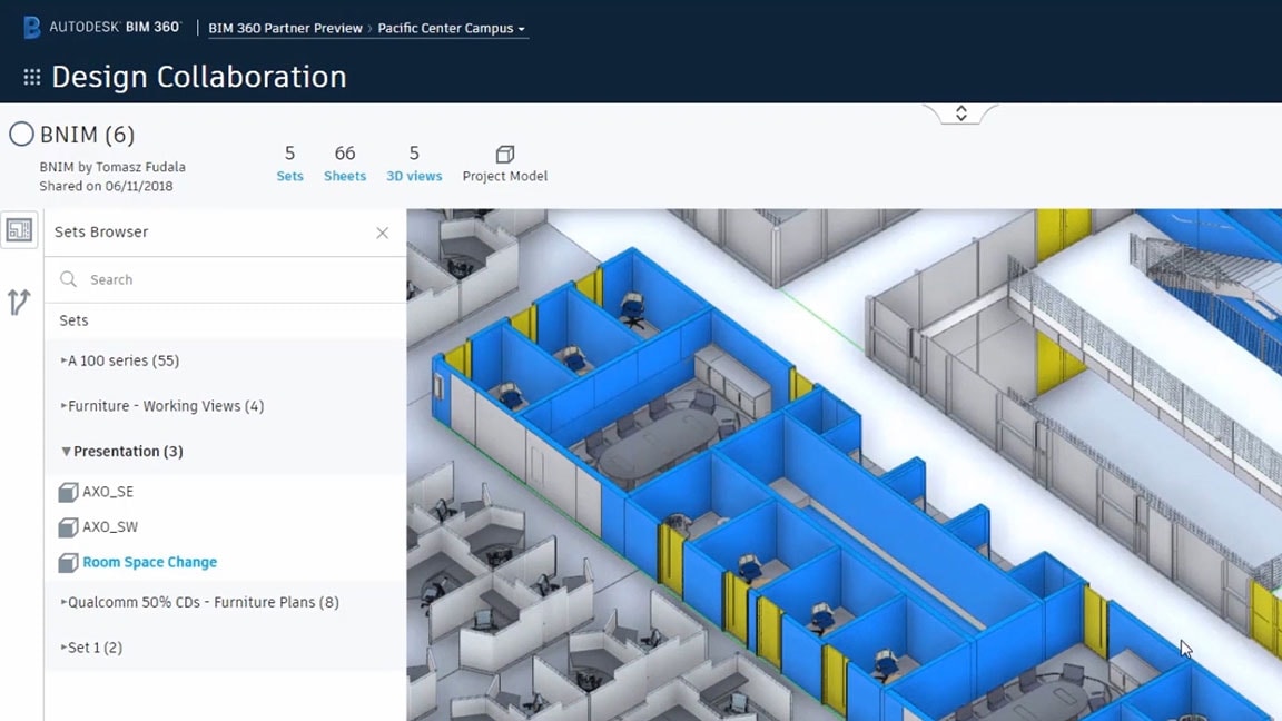
Abonnement A Bim 360 Design 2021 Acheter Bim 360 Design Autodesk

Abonnement A Bim 360 Design 2021 Acheter Bim 360 Design Autodesk

3d Modelling With Pix4d Or Autodesk Recap 360 3d Model Diy Drone Model

Autodesk Inventor 2020 What S New Frame Generator Youtube

Part 14 Advance Steel Connections Youtube

A Cluster Of Middle Eastern Villas Makes For A Great Multi Succulent Planter Succulent Planter Middle Eastern Succulents

Abonnement A Bim 360 Design 2021 Acheter Bim 360 Design Autodesk

Im320977 Anycad For Inventor Inventor Official Blog Autodesk Inventor Inventor Autodesk

1 Bending Plate Animation Autodesk Inventor 2020 Tutorial Youtube Autodesk Inventor Autodesk Tutorial

Komentar
Posting Komentar